OCT 27, 2026 · ANTIM LABS
Collider Generation & Cardboard Dynamics
Collider Generation
A common collider generation workflow starts with a visual mesh, runs convex decomposition (typically CoACD, as SDF colliders are too slow), on the mesh to get convex hulls which when joined together make the collision mesh. CoACD’s concavity metric considers both a shape's boundary and interior, which helps preserve openings, which makes it a strong method for generating colliders.
During contact, it is usually the case that physics step time and stability are inversely correlated with the number of convex hulls at the contact area. For this reason, the allowed deviation threshold between the collision mesh and visual mesh is constantly tweaked until there is a reasonable balance between the error and convex hull count.
This represents a tradeoff: Tightening the deviation threshold increases hull count, while having a lower threshold might allow for convex hulls that close off concavities that are important.
ADD ILLUSTRATION
For this reason, it is important for any automated collider generation system to be interaction and affordance aware – smooth over details that don’t matter, and spend hull count only where it does. Gizmo adds task context to that decision, and uses the visual mesh, generation prompt, reference images and supplied interactions to determine spatially varying levels of detail, and authors the colliders accordingly.
Example
Consider a whisk that a robot must grasp by the handle and place inside a kitchen drawer. A simplified convex hull around its wired head is sufficient to complete this task.
However, if the visual mesh of a whisk is passed to a naive CoACD system, it produces detailed hulls, matching the wiring of the visual mesh. This is almost certainly an excess, and adds simulation latency if a robot or other objects contact the head of the whisk.
ADD ILLUSTRATION VIDEO AND LATENCY STATS
For teams running simulation evals or synthetic data generation at scale, it would mean a massive slowdown. This example clearly underscores the need to have asset colliders purpose built for its intended task.
CARDBOARD BOX - VACUUM GRIPPER CASE STUDY
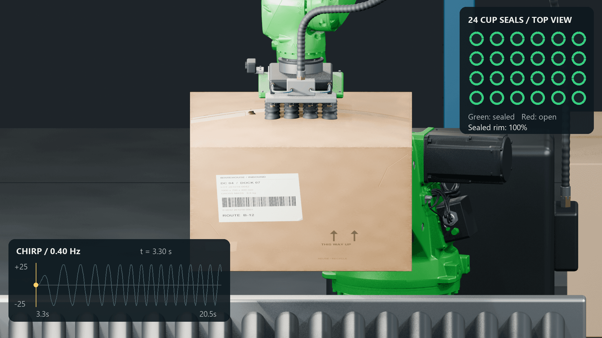
A suction gripper can grasp a cardboard box securely, but gradually loses its grip during certain movements. A useful simulator needs to be able to model this phenomenon correctly.
A grasp experiences a six-dimensional force–torque wrench: three components of force and three of torque. ADD LATEX
This cardboard handling case study details the modeling of a cardboard box in simulation such that it is able to model the slipping phenomenon, while satisfying a hard 4 ms simulation step time constraint, allowing for 250Hz robot control.
Since cardboard deformation and vacuum seal condition evolve under repeated loading, we also need to understand how the path through the wrench space affects the boundary between a secure grasp and slippage.
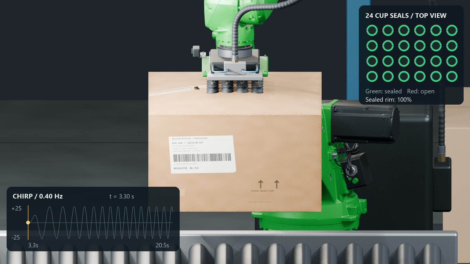
Several ground truth data points are collected using chirp signals applied to the vacuum gripper, to identify regions of the wrench space where the suction grippers lose their hold. The ground truth data helps to calibrate the simulation by fitting parameters.
Modeling
Challenge
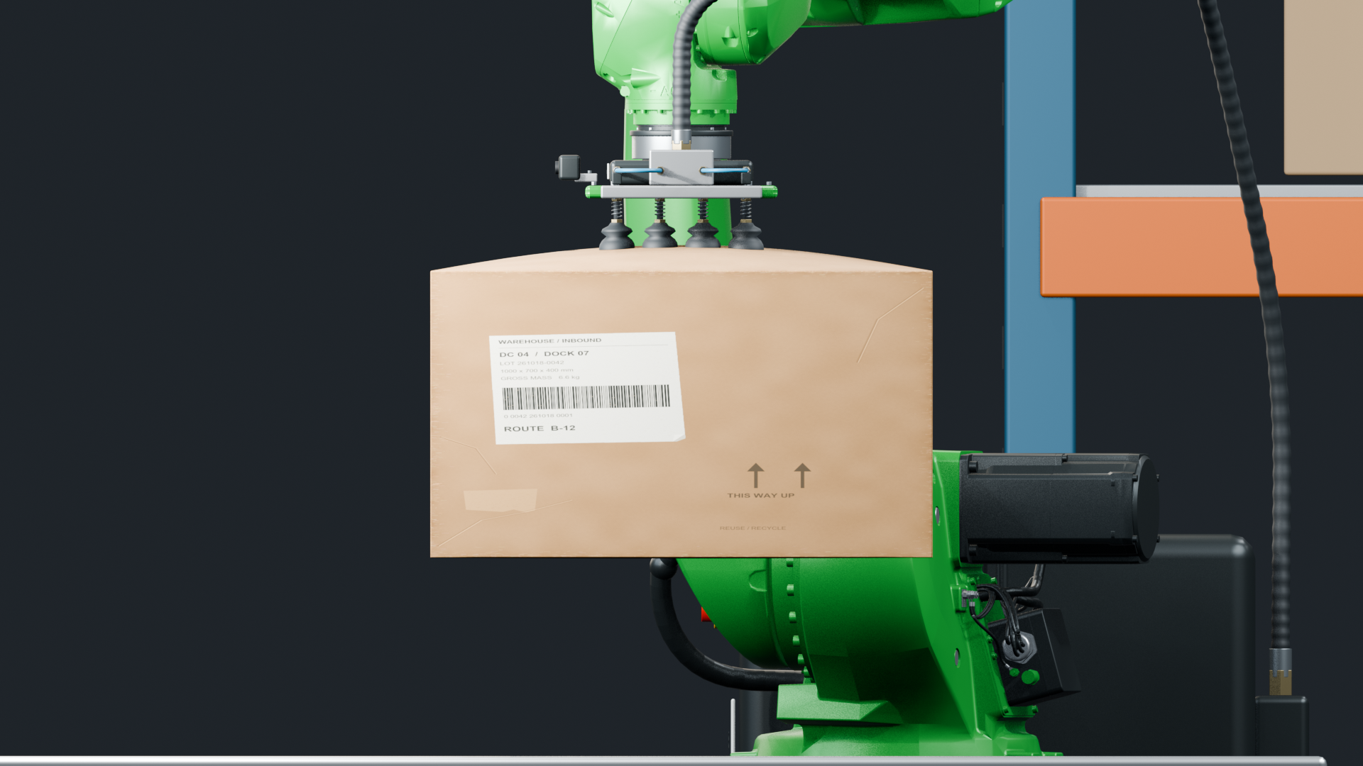
Cardboard surface bends under load, changing its shape and how forces are distributed across the grasp. The geometry and physics needed to model it satisfactorily lives in the millimetre-scale thickness of a cardboard surface.
The vacuum gripper suction cups are distributed compliant contacts allowing one part of a cup’s seal to open while the rest remains attached during peeling.
As the carton bends, gaps open along the cup rims. Air leaks in, which reduces suction pressure, and the remaining contacts carry more load. The model should also account for seal degradation from slipping and cup flexing.
Our Approach
Treating the cardboard surface as a rigid body makes it impossible to model the effects of traversing through the wrench space correctly.
On the other hand, naively using the publicly available deformable solvers like FEM or VBD from Newton leads to simulation speeds that are too slow to support 250 Hz robot control. This leads to a conundrum: rigid body modeling is incapable of expressing the phenomena we want, and full deformable modeling, while expressive, is too slow.
In our case, we want to be able to model broad panel bending and progressive detachment without paying for the ability to model arbitrary crushing at every mesh vertex. So, we model the cardboard as a limited deformable – we constrain the level of detail of deformation by restricting the number of modes used to represent the deformation. This leads us to a reduced-order mechanical representation.
Cardboard Model
We represent the cardboard using 9 bending modes for each of its 6 faces, with each mode’s amplitude evolving in response to applied forces. Together with six rigid-body coordinates, this gives a 60-coordinate cardboard model. Even a reasonable mesh representation of a 22 × 8.5 × 30 cm box leads to 714 vertices and 2,142 positional coordinates. Naively reducing the mesh density does not work because such a mesh is unable to represent the smooth cardboard bending.
By limiting our focus to the kinds of deformation we observe in practice, our representation substantially reduces the computational workload by reducing the coordinates by approximately 35x.
Our reduced-order system represents surface displacement as a weighted sum of bending modes:
Here, represents a fixed spatial deformation mode, while qₖ(t) is its evolving amplitude.
We couple this model to distributed suction contacts, and solve the resulting interactions efficiently.
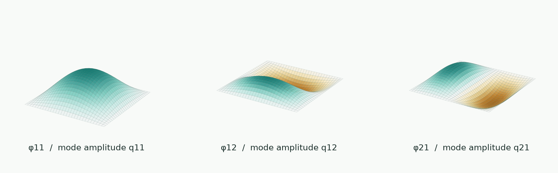
A small vocabulary of shapes, many possible responses: Three illustrative basis functions from the nine used per face.
Vacuum Gripper Model
The gripper uses a 6 × 4 array of suction cups, and spring stiffness and damping dictate how each cup responds to loading. Each cup’s chamber pressure follows a balance between pumping and incoming air. This simplified model captures the cup’s mechanical and pneumatic response without simulating a detailed rubber mesh. More modeling details are given in the appendix [LINK].
Coupling
The cardboard and suction cups are coupled through their contact geometry and forces. At each physics substep, the cardboard’s bending modes determine the surface position and slope beneath each cup, which set the rim gaps and contact response. The resulting pressure and contact forces are projected back into the cardboard’s modal coordinates, while equal-and-opposite loads act on the cups’ extension and tilt coordinates.
Resulting Speedup
A simple indentation test on our cardboard box constitutive model reduced the median physics step time from 22.7 ms to 0.46 ms in a single-box comparison—approximately 49× faster than the full-shell VBD implementation.
The coupled cardboard-vacuum gripper model to 2.07 ms at the 99th percentile, lower than our 4 ms target for 250 Hz robot control.
Complete physics step time (ms)
| Simulation | Implementation | Median | p99 | Maximum |
|---|---|---|---|---|
| Indentation | Reduced model / laptop CPU | 0.46 | 8.56 | 10.96 |
| Indentation | Experimental VBD / RTX 4050 | 22.70 | 32.36 | 44.39 |
| Cardboard + 24 cups | Reduced model / Modal CPU | 1.53 | 2.07 | 17.39 |
APPENDIX
Vaccum Gripper model details:
Each suction cup is represented by three mechanical coordinates: axial extension and two tilt components, instead of a fully deformable rubber mesh. Writing these as z = [δ, α, β]ᵀ, we model the bellows as an overdamped spring–damper system:
C ż + K z = fₚ + fᵣ
Here, C and K are the damping and stiffness matrices, while fₚ and fᵣ are the generalized pressure and contact loads. At a rim point (x, y), the cup’s local displacement is u(x, y) = δ + αx + βy. This allows one side to lift while the opposite side remains in contact, using only 72 mechanical coordinates for the 24-cup array, with explicit extension and tilt limits.
Each cup also has one chamber-pressure state and 12 circumferential seal states. A sector’s seal fraction s relaxes toward a gap-dependent equilibrium s*(g):
ṡ = [s(g) − s] / τ*
The time constant τ differs for opening and resealing. Leakage through the remaining contact band follows a thin-gap flow model, capped by compressible orifice flow; chamber pressure evolves from pumping, leakage, and volume changes as the bellows extends. Pressure-dependent loads act across the cup footprint, while the lip supports compression and friction. This separates suction from physical contact, allowing partial peeling and pressure loss without treating attachment as a binary constraint.